
Punching File Holes in Copies
Finisher FS-531 mounted with Punch Kit PK-512 or Punch Kit PK-513 can punch file holes in copies. Punch and Staple are compatible.
Original | Output | ||
| [2-Hole Punch] | ||
[Left] | [Right] | [Top] | |
 |  |  | |
[3-Hole Punch] | |||
[Left] | [Right] | [Top] | |
|
|
| |
[4-Hole Punch] | |||
[Left] | [Right] | [Top] | |
|
|
| |
[Swedish 4-Hole Punch] | |||
[Left] | [Right] | [Top] | |
 |  |  | |


Do not punch special paper type such as labels or tracing paper. Punching in special paper may cause unexpected machine trouble.
Item | Description |
|---|---|
Number of punch holes | - PK-512 |
Hole diameter | 2 holes: 6.5 mm |
Hole pitch | - PK-512 |
Paper size | A3 |
Paper weight | 64 g/m2 to 128 g/m2 / 17 lb Bond to 33 lb Bond |


Be sure that the side guides of the source tray are securely aligned to the paper loaded in that tray. Otherwise, copies may not be punched in position.
If ATS (automatic tray switch) functions while punching operation is in progress, punch holes may be off the position.
Punch mode is unavailable for paper sizes other than [standard] ([Detect Size Setting], [Custom], [Tab paper]).
Position the original.
Press the [COPY] tab to display the [COPY] screen.
Press [Output Setting].
The [Output Setting] screen is displayed.
Press [Punch] under [Output].
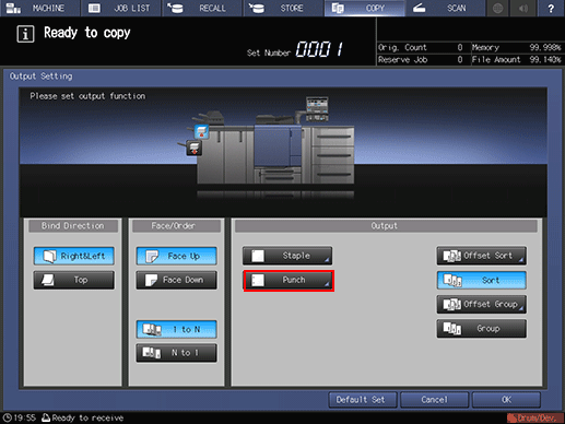
The [Punch] screen is displayed.
Press the desired key to select the punch type and position.
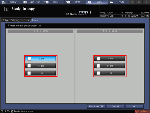
Press [OK].
To resume the previous setting, press [Cancel]. To cancel the Punch function with the current setting saved, press [Function OFF]. The screen returns to the [Output Setting] screen.
The front image of the machine provided on the [Output Setting] screen shows that the primary (main) tray is currently selected as an output tray.
Press [OK] on the [Output Setting] screen.
An icon representing specified output mode is displayed under [Output Setting] on the [COPY] screen.

The primary (main) tray gradually goes down while printed materials are output. DO NOT allow any object to interfere with the operation of the primary (main) tray on the left side of the finisher, as any interference may cause damage to the finisher.