
Auto Ring Binder GP-502

No. | Name | Description |
|---|---|---|
1 | Ring binder top cover | Opens upward for removal of mishandled paper. |
2 | Display panel | Displays the status of the ring binder, position of paper jam, alarm for supplies and disposals, and counts/versions. |
3 | Lock release handle | Pulled to unlock and open the upper unit of the ring binder. |
4 | Booklet tray | Holds ring-bound booklets. Withdraw the tray to take out the output booklets. |
5 | Ring binder front door | Opens to allow removal of mishandled paper or waste paper punched out. |
6 | Ring binder front door handle | Held to open the ring binder front door. |
7 | Power switch | Turns on/off the power of the ring binder. |
8 | Power plug | Supplies power to the ring binder. |

Keep the power switch turned on for the ring binder. Turning it off will not only deactivate this machine but disable the bypass function to convey paper to the downstream finisher.
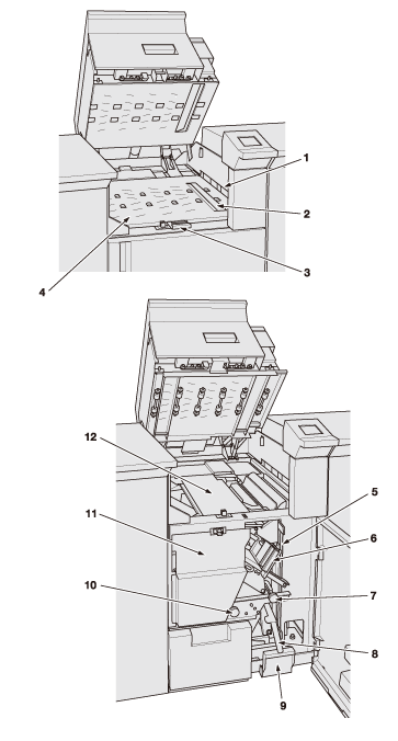
Internal view of Auto Ring Binder GP-502
No. | Name | Description |
|---|---|---|
1 | Paper inlet | Ejects paper fed to the ring binder. |
2 | Paper distributing section | Delivers paper fed to the ring binder into the binding section, or bypasses it to the downstream finisher. |
3 | Handle[GP1] | Held to open the bypass deck upward. |
4 | Bypass deck | Bypasses paper fed to the ring binder straight to the downstream finisher. |
5 | Vertical paper path | Feeds paper to the punching device. |
6 | Bind part drawer | Holds bind parts. |
7 | Knob[GP3] | Turned counterclockwise for removal of paper jam. |
8 | Lever[GP2] | Opens leftward for removal of paper jam. |
9 | Punch scrap box | Withdrawn for removal of punch scraps. |
10 | Knob[GP4] | Turned clockwise for removal of paper jam. |
11 | Paper stacker | Aligns sheets to be bound, and delivers bound booklets to the booklet tray. |
12 | Binding section | Binds a set of paper with a bind part. Take a look when trouble occurs on bind parts. |